Category Archives: Maker

Laser Turret

Seneca Ridge Middle School students at the workshop

The Laser Turret project was built for a STEM technology workshop that I organized at the local middle school. “Laser Turret” was the project that was chosen among several options I offered at a talk on computer engineering and technology careers.

Weapons System Design

In order to be cool enough to impress kids, I wanted the turret to have motorized 2-axis aiming to pan and tilt the laser and fully automated aiming and firing. In order to designate its own targets, the turret would need some kind of sonar/radar target scanning and, of course, a working laser, lights and sound.

I wanted to show that we could build this new idea from scratch, so the whole thing would start with an original design that would be 3D printed to make the turret parts.

Components

Nine-gram micro servo

Before we could design the turret itself, we needed to choose the electronic and mechanical components that would define its operation. We wanted to try to stick to as simple a design as possible, so that meant thinking small.

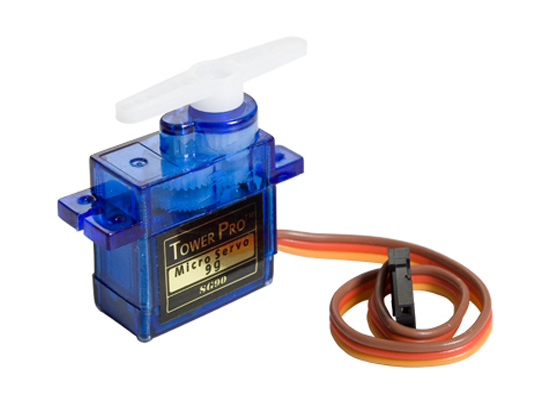
The tiny 9g micro-servo is about as small and simple as mechanical output gets! 180-degrees of roboty sound and motion driven directly by one 5v pin.

HR-SR04 Ultrasonic Sensor

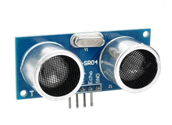
To let the turret scan its environment for enemies, we imagined a scanning sonar solution based on the HR-SR04 ultrasonic sensor. This common starter-kit component is made to sense distance using high-frequency sound echos, but I saw no reason why we couldn’t spin it around and “look” in all directions.

Five milliwatt laser diode

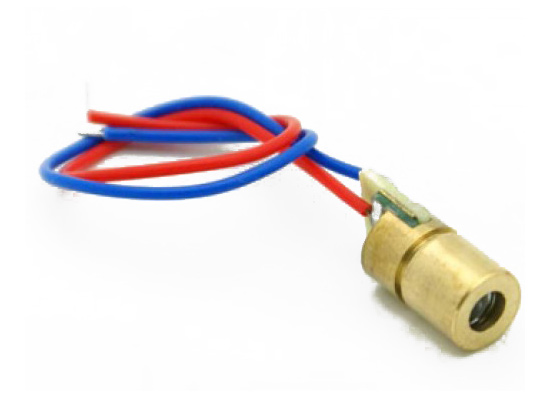
The laser itself is a genuine 5-milliwatt 650-nanometer laser, which is a fun way to not have to say that’s it’s a 35-cent laser-pointer diode.

So that’s one servo for pan, one servo for tilt and a third to rotate our scanning sonar back and forth. Add in one ultrasonic sensor, one serious-looking laser and a handful of variously-colored LEDs and wires and we’re still under $10 so far.

The turret still needs brains, a control system to process the input signals, select targets, align the laser and send those photons down range. A compact weapons package like ours deserves a sleek piece of miniaturized computing power.

Adafruit Metro Mini
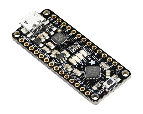
The AdaFruit Metro Mini answers the call in  black stealth pajamas. The Metro Mini packs a 16Mhz ATmega328 processor, serial communication and 20 GPIO pins into  its thumb-sized package and looks super-cool doing it.

Design & Modeling

Rather than using an existing design, we had decided to create our turret from scratch. The first step was to decide how the turret would work mechanically, where the servos would go and how they would move the parts of the turret.

Here’s what we came up with.

Finished turret model

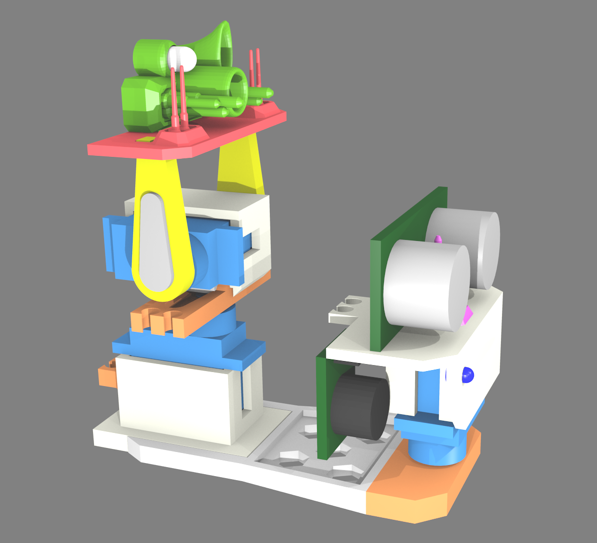
We threw away a number of more complex ideas and settled on a simple design where the laser can be stowed out of view and then pop up into pan & tilt action when an enemy is detected.

Turret Front View
Turret Front View

From the side, you can see the rotating sonar platform as well as the pan and tilt laser weapons platform.

Turret Side View
Turret Side View

The model was built in Blender and refined with several tests using Ken’s 3D printer to ensure the eventual fit of the final parts.

Test parts to refine fit

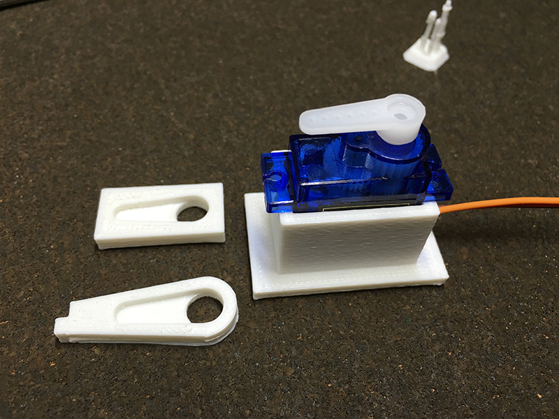
Here’s one of the test prints that shows a servo inside an enclosure that served as the model for all the servo housings. The loose square piece was used to test the fit of the servo arm, mounted on the servo. Below the test piece, you can see the final printed arm that was made from the test part’s geometry.

Exploded parts view
Exploded parts view

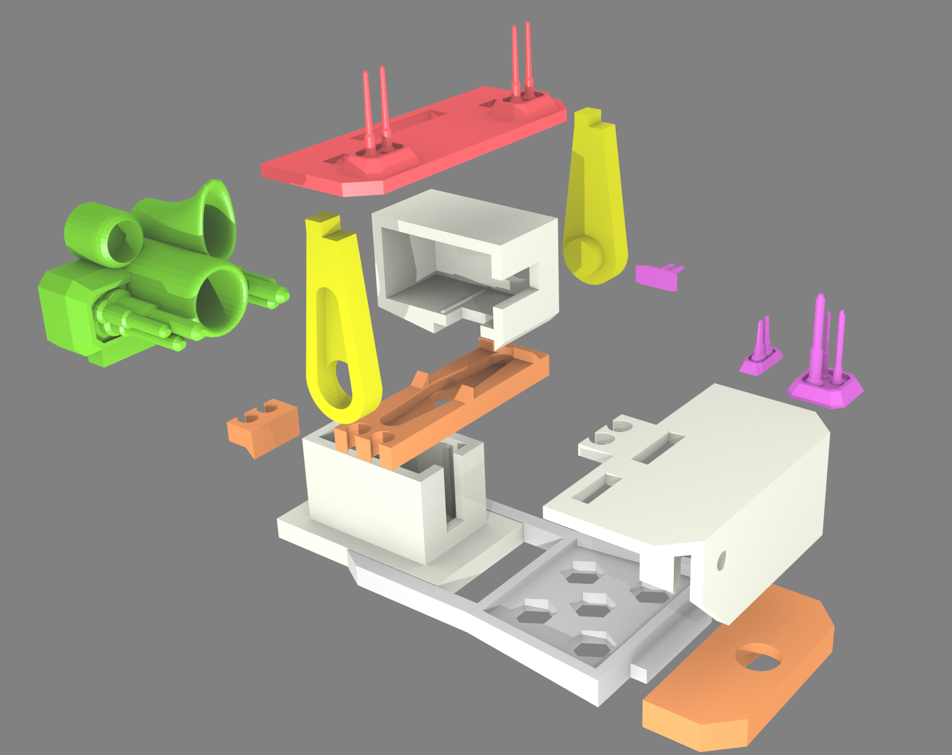
The design allowed for certain pieces to lock together and for others to rotate against each other.  You can see some of the types of connections in this exploded view.

The weapons array consisted of a large “flash” LED to enhance the firing effect as well as a red LED that would mimic the laser without the eye-damaging laser light. The laser itself would only be active for less than a tenth of a second, but it was enough to mark you with a red laser dot if you were “hit”.

Once complete, the laser turret model was virtually disassembled and the pieces were aligned for the 3D printing of the parts.

3D printing layout
3D printing layout

Programming

Programming the turret consisted of three simple, specialized components. In addition to a master command program, some additional code went into managing the sonar system and the laser platform sub-components.

Programming model
Turret system component model

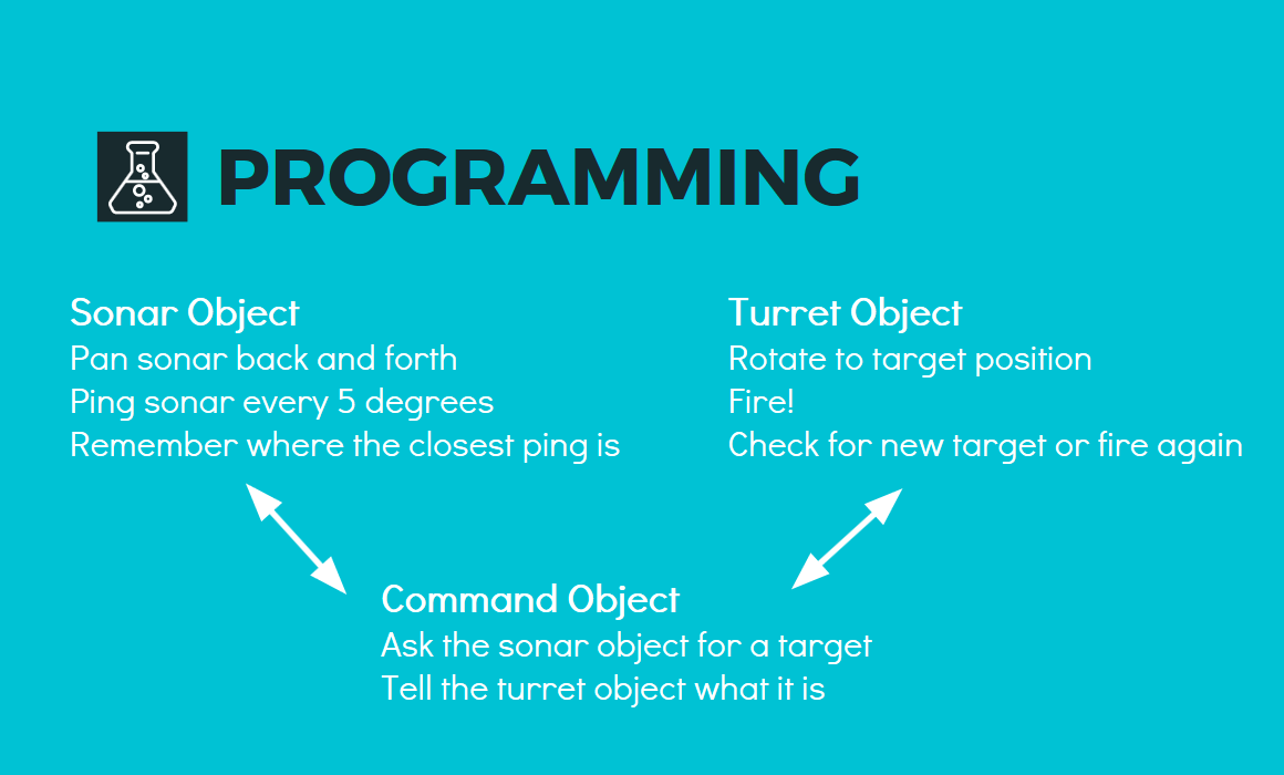
By delegating target-acquisition and firing to the sub-components, the command program became very simple, only needing to ask the sonar for a target and then handing it off to the firing platform.

Pinout

Connections between the turret and the microprocessor

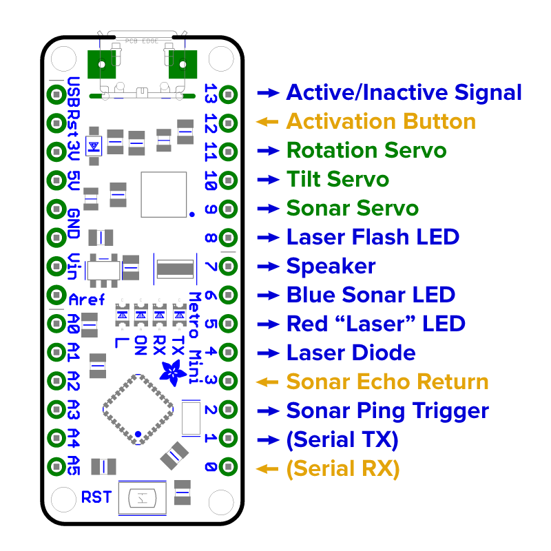
Once the physical components and the programming of the turret were defined, it was time to look at the wiring for the AdaFruit Metro Mini electronic control system.  For the programming to work, all the servos, LEDs  and other components needed a connection to the microprocessor.

I also created a small operator panel with an activation button and two small status LEDs. This diagram shows how it all worked out.

Assembly

3D-printen turret parts
3D-printed turret parts

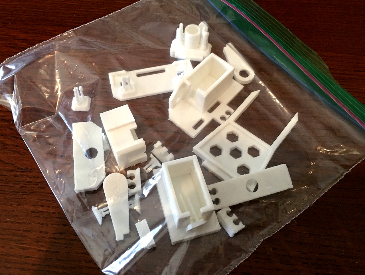
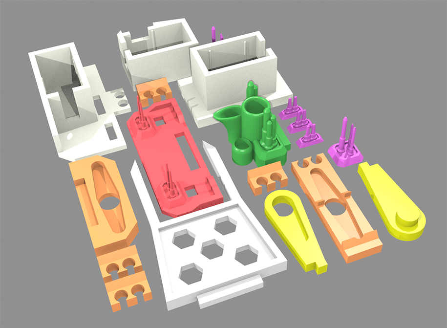
The turret came back from the printer as a baggy full of loose parts. Shout out again to Ken and his Flashforge Dreamer. Our next step was sorting through all the parts and beginning the assembly.

Printed parts and components

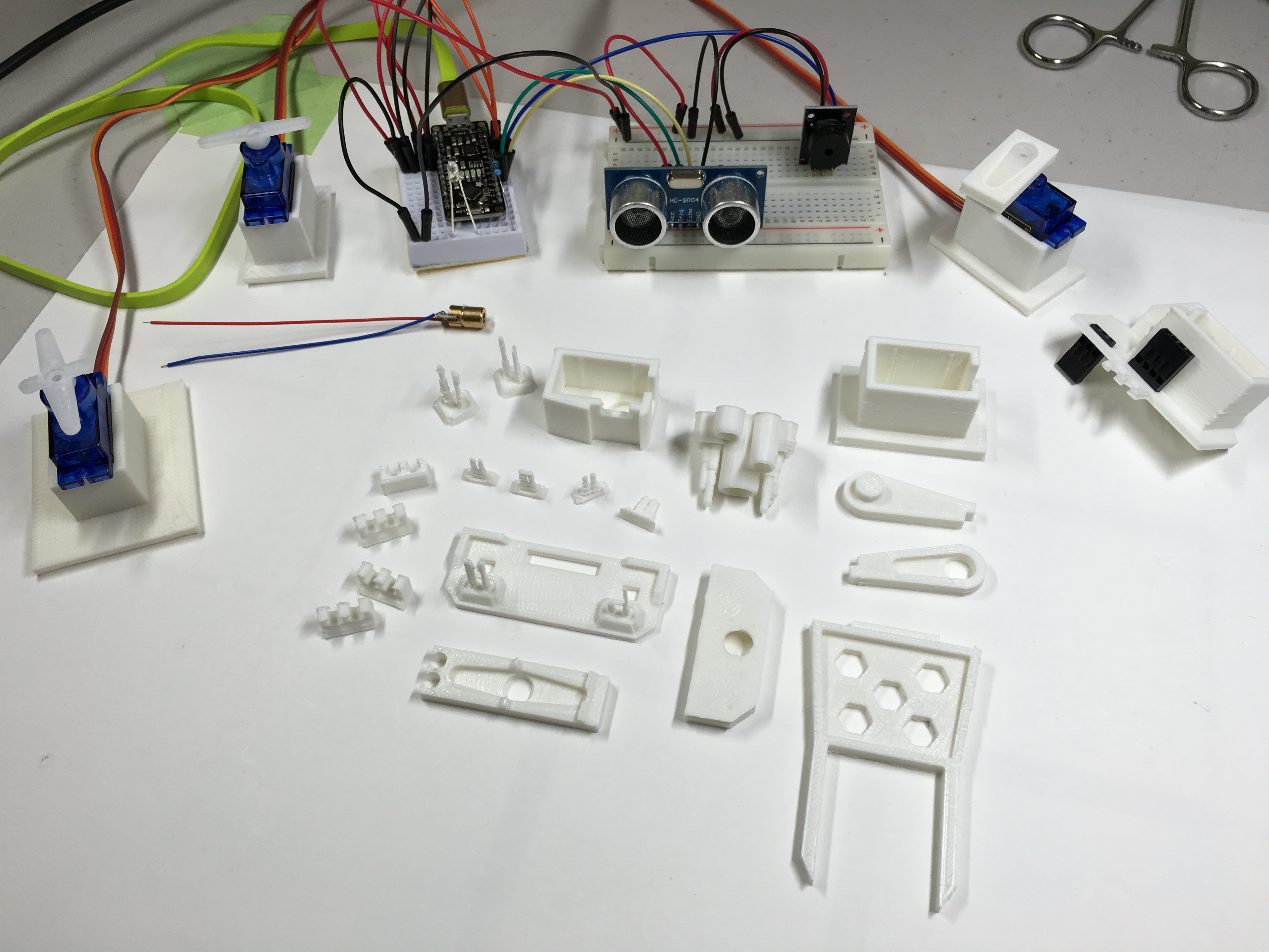
Here’s all of our turret parts arranged for assembly.

All we needed was an assembly crew.

Turret assembly crew

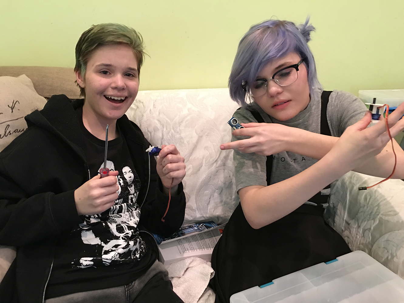
And here they are, my daughters Maddie and Cas, who were kind enough (at least for a little while) to put up with a lot of fidgeting with tiny wires.

Turret wiring harness (28 AWG)

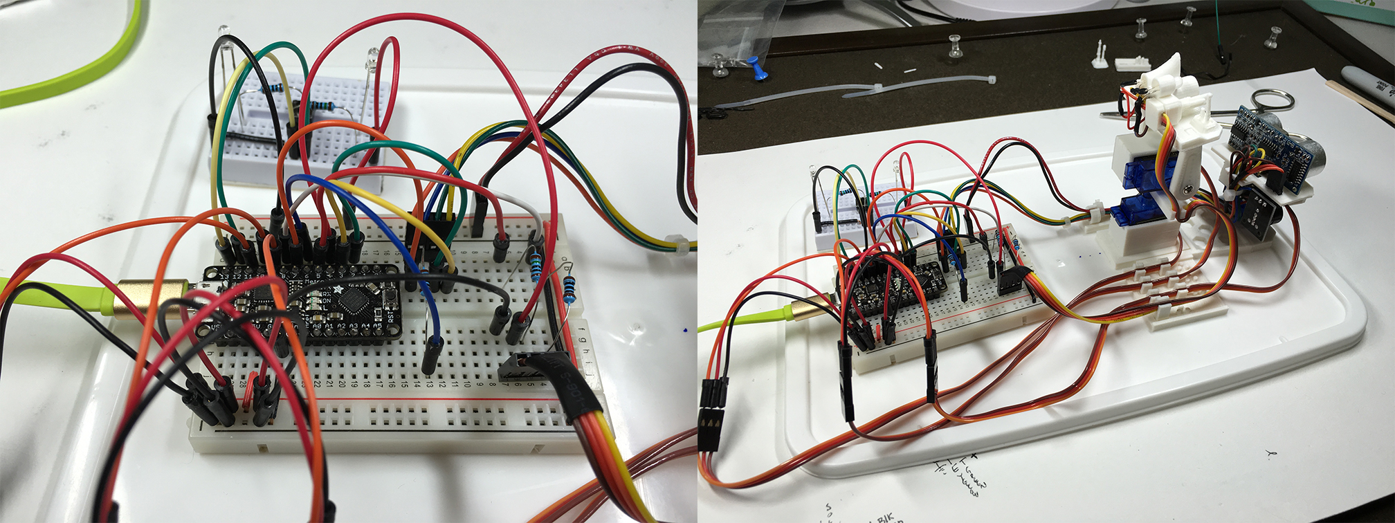
These two images show the connections to the Metro Mini and the completed turret. Even with 28-guage wire, the wire (and its weight/tension) contributed significantly negatively to optimal turret operation. In other words, maybe I should have used even smaller wires… or better yet, a BIGGER turret!

Next time, perhaps.

Testing & Demonstration

Live-fire testing in a classroom environment

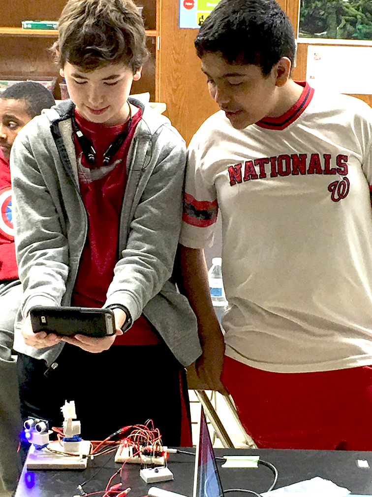
Cas and Maddie helped me test the turret in a large basement room. A few tweaks to the programming was all that was needed to start tracking and firing at the girls as they moved around the room.

At the middle school, the kids enjoyed trying to evade the automated firing system, but were quick to exploit the limitations of the platform, such as having everyone attack at once. Sun Tzu might be proud, Grand Moff Tarkin, maybe not so much.

Robot Tic-Tac-Toe

Robot-in-Training
Robot-in-Training

 uArm Metal Autonomous Tic-Tac-Toe Robot

Welcome to the project page for the Autonomous Tic-Tac-Toe Robot. I’ll update this page periodically with any new progress if you want to follow along.

Goals

The overarching goal for the robot is to play fully autonomously, like a human. This defines five major components I decided were needed to fulfill that goal.

  • Understand the Game
    The robot must understand how the game is played and have some sense of a strategy for winning.
  • Sense the Board
    The robot must be able to interpret the moves that the player makes and understand the positions of  the pieces on the board.
  • Move the Pieces
    To robot must make its own moves at the appropriate times, using whichever marker has been assigned.
  • Play Autonomously
    All the programming must reside within the robot itself and it should play without any connected computer or external signal.
  • Convey Emotion
    This is a “stretch goal” to see if the robot can convey emotion to the player, based on the status of the game.

About the Robot Arm

The robot arm is a uArm Metal, made by UFactory. It was created initially as part of a Kickstarter campaign and is now in production.

The uArm Metal
The uArm Metal

The uArm is a 4-axis robotic arm with three degrees of freedom as well as a hand-rotation axis. It’s based on a design for an industrial pallet-loader and is thus best suited for positioning and stacking items in a 180-degree operating area.

The uArm is controlled by an on-board Arduino microprocessor and is fully open source.

Understanding the Game of Tic-Tac-Toe

There are lots of resources on the web that will tell you how to play tic-tac-toe and there are many ways to teach a computer how to implement game strategy. For reasons related to the memory available on the microprocessor, I wrote an algorithm based on logical human strategies such as, “move to an open corner such that a block does not result in two in-a-row for the opponent.” The computer must understand both how to translate that strategy into an appropriate move and also when to apply that particular strategy.

The initial version of the strategy algorithm worked so well that the robot was unbeatable and therefore, noted my daughter Cassie, no fun at all.

Challenge the Robot
Challenge the Robot now on the Web

A final version of the robot game-logic incorporates three difficulty levels based on characters I hope to explore further in the emotion section.

You can play tic-tac-toe against the actual game algorithm programmed into the robot by clicking here, or on the image of the game board.

Sensing the Board

Computer vision is a computationally-expensive thing and beyond the reach of most small micro-controllers. The robot solves this problem with the Pixy (CMUcam5) from Charmed Labs that employs a dedicated on-board processor for simple object recognition.

This short video gives a good overview of the vision system.

The Pixy allowed me, the programmer, access to a much simpler stream of information where blobs of different color are represented as screen rectangles. This helps a lot.

Moving the Pieces

Moving the pieces was pretty straightforward using the built-in programming of the uArm, but I thought it could be better. I made a number of improvements to the way the arm worked and contributed those changes back to the open-source project where they’re now part of the arm’s programming. Pretty cool!

The video below also shows an example of common engineering math. You’ll find that it’s not really so hard!

Playing Autonomously

Combining the vision system with the robot’s movement system is the next challenge!

The robot’s micro-controller is part of a custom circuit-board developed specifically for the uArm and is therefore optimized for control of the robot. Without access to the input/output pins normally available on an Arduino microprocessor, the options for interfacing the vision system with the robot’s hardware are quite limited.

Thus, I haven’t yet been able to run both vision and movement from the single robot micro-controller. I have some ideas, though!

Conveying Emotion

If you have seem my STEM talk on Computer Engineering or the movement video above, you’ve seen that the robot is capable of expressing at least a few different emotions. I hope to build out this capability once the other issues are solved.

Final Update

Thanks to a comment on one of the YouTube videos, I realized today that it had been more than a year since I promised to update this page with progress. So here’s what happened.

Even if two halves work flawlessly, there will be unforeseen issues when they try to work together. When the only communication channel your onboard computer has is being used for a camera, it is impossible to debug a robot.

My approach was to rig a software serial port off of two unused uArm board pins strung to another ‘debug’ Arduino that would simply proxy data from the uArm to the computer via USB. Once robot debugging was complete, the external Arduino could be disconnected and the robot would run autonomously.

In the end, grounding problems between the Arduinos and glitchy Pixy performance due to its not getting enough juice off the uArm board were enough to ground the project.

I’m more a software guy. When it comes to low-level things like wire protocols and power systems, I want someone else to handle them. I had made each half work, and that was all I needed! 🙂

3D Printing A Spaceship

The Artemis transitions from virtual to physical

Today at work, I printed a spaceship!

One of the best things about my job is that I’m surrounded by tremendously smart engineers that fully appreciate the benefits of geeking out. Over the history of our small start-up, my colleagues have brought all manner of their creations into the office including home-built telepresence robots, processor-controlled Christmas decorations and a homemade quad-copter drone that was so good that it was able to crash into a tree way over on the far side of the parking lot.

But this week, we were the kings of Nerdville when Steve brought his new 3D printer in for all of us to play with.

Continue reading 3D Printing A Spaceship